Graphic Model of Organizational Structure
An element of the organizational structure is a component of the graphic model (department, job position, group of employees). All the main elements and their functions are described in the Organizational Structure Modeling section.
Each element has its own identifier (UID). For more information on identifiers, see the respective Help page.
To open the settings window of an element, mouse over the desired element on the modeling sheet and click the right mouse button. In the provided window, select Settings.
Depending on the element type, the settings may vary.
The required fields in the settings window are marked with a red asterisk .
.
Job Position settings window
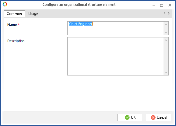
The Job Position settings window features two tabs: Common and Usage (Fig.1).
|
|
|
Fig.1. Job Position configuration. Common tab.
|
On the Common tab enter the title of the job position in the Name field. This name will be displayed both in ELMA Designer and Web Application, after the organizational structure model is published.
You can add a description of the job position in the Description field.
The is Head of Department option is only available if the Job Position belongs to a department. With this option you can specify that the Job Position is the Head of the department.
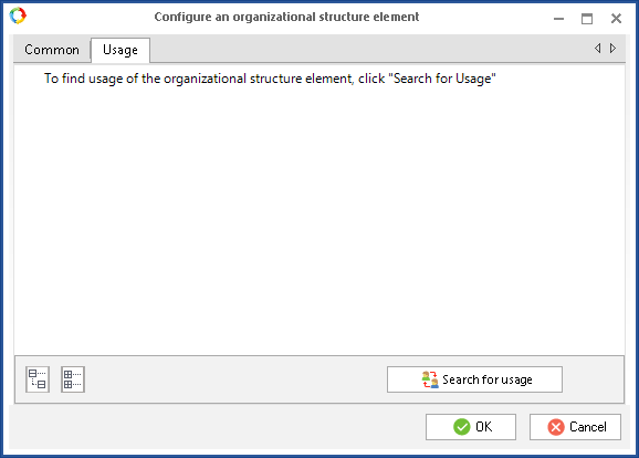
On the Usage tab (Fig. 2), you can see if the element is used by any ELMA application. For that, click Search for usage.
Group of Employees settings
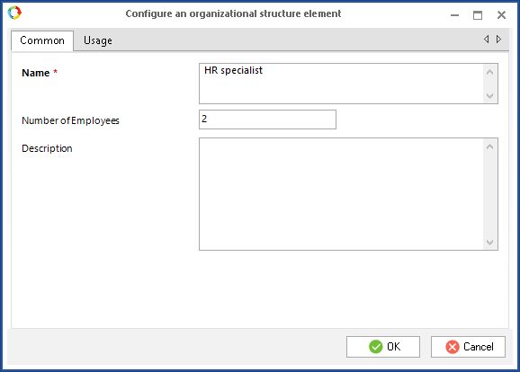
The Group of Employees settings window features two tabs: Common and Usage (Fig.3).
|
|
|
Fig. 3. Group of Employees configuration.
|
On the Common tab, enter the title of this Group of Employees in the Name field. This name will be displayed both in ELMA Designer and Web Application, after the organizational structure model is published.
You can add a description of the group in the Description field.
In the Number of Employees field, specify the number of employees included in this group. This field is only informative, it is not taken into account when users are appointed to job positions.
On the Usage tab (Fig. 2) you can see if the element is used by any ELMA application. To do so, click Search for Usage.
Department settings
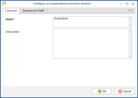
The settings window of the Department element features two tabs: Common and Department Staff (Fig.5).
|
|
|
Fig.4. Department configuration.
|
On the Common tab, enter the title of the Department. This name will be displayed both in ELMA Designer and Web Application, after the organizational structure model is published.
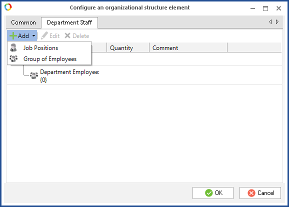
Give a short description of the department in the Description field. On the Department Staff tab you can create a list of the department employees: simply click Add. In the expanded list you can select a job position or a group of employees who work in the department (Fig.5).
|
|
|
Fig.5. Department Staff tab of the Department element.
|
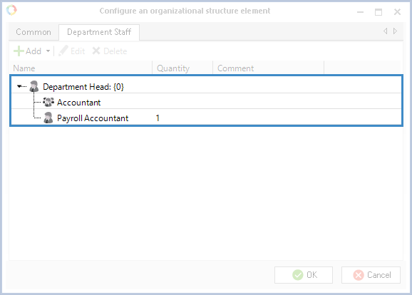
Once a job position or a group of employees is added to the department, they will appear in the Department Staff table. The Name column specifies the name of the element included in the department. The Comment column shows a comment on this element, which was previously added in the Description field, on the Common tab (Fig.6).
|
|
|
Fig.6. Element configuration. Department Staff tab.
|
The  and
and  buttons can be active or inactive: If an element is selected in the table, they are active. Otherwise, they are inactive.
Click Edit to open the settings which can be edited.
|
|
|
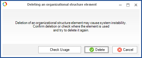
Fig.7. "Deleting the organizational structure element" window.
|
Annotation
An Annotation is placed on the modeling sheet, and contains a comment on a certain element of the organizational structure (Fig. 8).
|
|
|
Fig. 8. Example of using an annotation in the modeling sheet.
|
Adding an Annotation to the modeling sheet
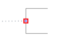
To add an Annotation to the modeling sheet, select it in the Organizational Structure Elements side panel and drag it to the modeling sheet. Then click the Connector button in the top toolbar, mouse over the Annotation element in the modeling sheet and draw a line to the connection point of a desired element of the structure. There can be only one outgoing connector from an Annotation (Fig.9).
|
|
|
Fig.9. Connection point of an Annotation.
|
There is another way to add an Annotation to the modeling sheet: click the Index button, place the pointer over the element on which you wish to comment. Green icons representing other elements will appear around it. Select the Annotation element and place it on any free space on the modeling sheet. The connection line between the Annotation and the other element will be created automatically.
Annotation settings
To open the Annotation settings, right-click on the element and select the Settings option in the appeared context menu.
The settings window of the element features two tabs: Common and Usage (Fig.10).
|
|
|
Fig.10. Annotation settings window.
|
The Common tab has a required Name field, where you should specify the name of the Annotation as you want it to be displayed on the modeling sheet.
In the Description field you can make a comment about the element.
The check usage feature is not available for an Annotation.
Group
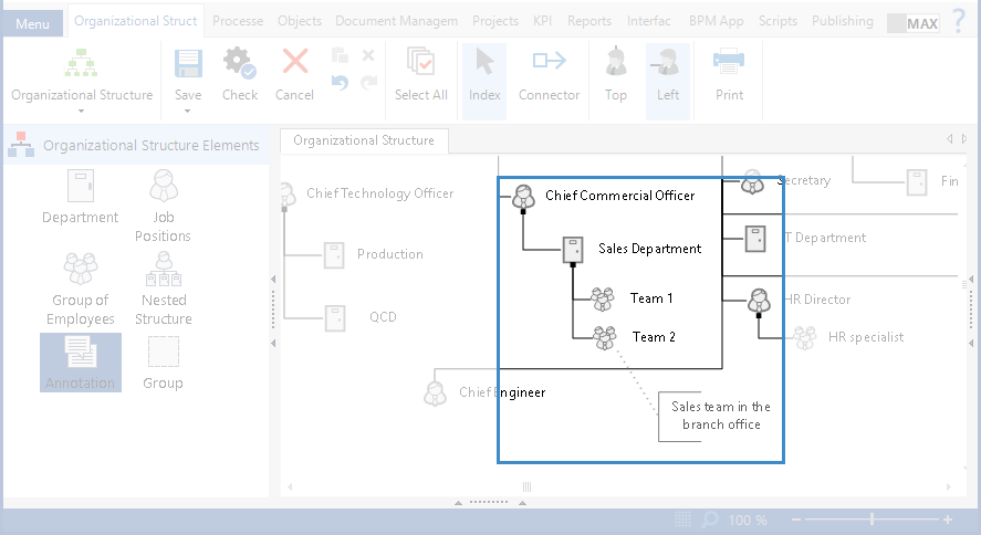
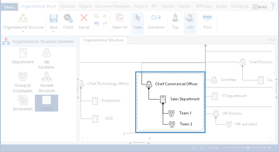
With the Group element you can group several elements in one box, without changing the overall hierarchy. It is useful if you want to group various departments by a certain attribute. For example, you can group the Financial and the Economics departments into one "finance group". This makes the model more readable (Fig.11).
|
|
|
Fig. 11. Uniting elements in a group
|
To add a Group to the modeling sheet, select it in the Organizational Structure Elements panel and drag it to where the elements that you want to group are located.
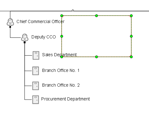
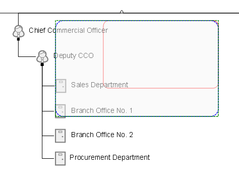
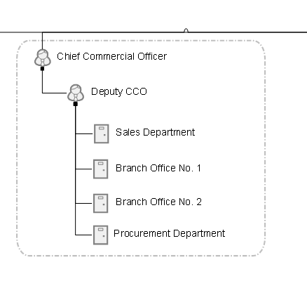
You can resize a Group on the modeling sheet. Left-click on the element to select it: It will then look like a rectangle with dots on each side (Fig.12). Click on one of the dots and pull it to the side (Fig.13). This way you can change the height and the width of the element until it reaches the right size and all the other elements fit in. The group is represented as a dash line box (Fig.14).
|
|
|
Fig.13. Changing the size of a Group element.
|
|
|
|
Fig.14. Organizational structure elements united in a group.
|
Group configuration
To open the settings of a Group, mouse over the element and double-click on it.
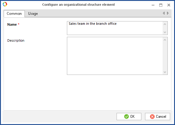
The Group settings window features two tabs: Common and Usage (Fig.15).
|
|
|
Fig.15. Group configuration.
|
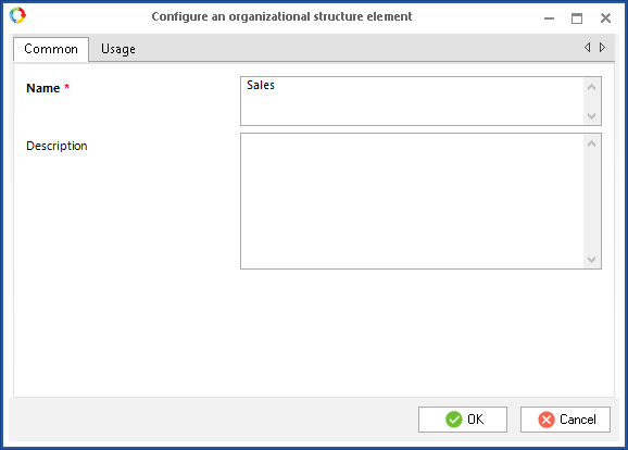
The Common tab has a required Name field, where you specify the name of the Group as you want it to be displayed in the modeling sheet.
In the Description field you can make a comment about the group of elements.
There are two ways to delete a Group element: left-click to select the element and press Delete on your keyboard; mouse over the group and click the right button to open the context menu; select Delete.
Deleting a group in no way impacts the elements within the group.
See also:
Copyright © 2006–2019 ELMA