Modeling Business Processes
1. Creating and modeling business processes
ELMA Designer allows modeling business processes in a user-friendly graphic interface. BPMN is used for modeling.
1.1 BPMN
BPMN is very simple and visual. A rectangular shape is a swimlane. It’s a BPMN element used to separate and organize activities by participants. Each Swimlane represents a participant; activities placed in the Swimlane are activities that the participant has to perform.
Thus, each process is a chain of connected activities. You can find a full description of Activities in ELMA Help.
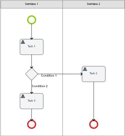
Fig. 1 ELMA Designer. Graphic model
ELMA implements various activity types, but in this manual, we will describe only one activity type: a User Task.
A User Task is work that must be done by a user. When users finish their work, they must enter certain information in the form and click one of the available buttons to continue. In other words, these user tasks are personal tasks of the system users.
Another element of a business process model is a Gateway. A Gateway is a branching point that controls the process flow by splitting and merging it. You use this modeling element to:
- Check if a condition for the execution of a business process is true or false and select one Sequence Flow from several Sequence Flows (E.g., system checks the amount of a contract. If the amount of the contract is low, the simplified approval procedure will be carried out).
- Create a parallel flow. (E.g., various employees simultaneously approve the contract).
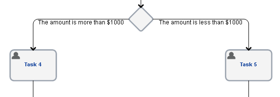
Fig. 2 ELMA Designer. Graphic model
An Event is another graphical element, which is used for process modeling.
- Start Event. A Start Event shows where a process starts. In BPMN, the Start Event is a small, open circle, which is always the first element of the business process diagram.
- End Event. An End event marks where a process ends. Within the process, multiple End Events might exist depending on the number of process paths. In BPMN, the End Event is a small, open circle.
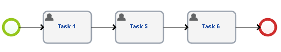
Fig. 3 ELMA Designer. Graphic model
For more information about BPMN, see ELMA Help.
1.2 Creating a new business process
When you start ELMA Designer, the Organizational Structure tab opens. It contains a scheme that shows the structure of an organization and the relationships of its units and job positions.
To create a business process, go to the Processes tab. This tab shows a list of existing processes. If necessary, you can group the processes by departments or business activities.
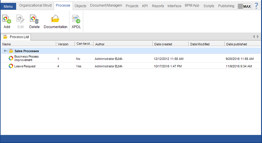
Fig. 4 ELMA Designer. Processes tab
To create a new business process, click the Add button on the toolbar. The process creation wizard starts and the dialog box opens asking you to configure the business process parameters.
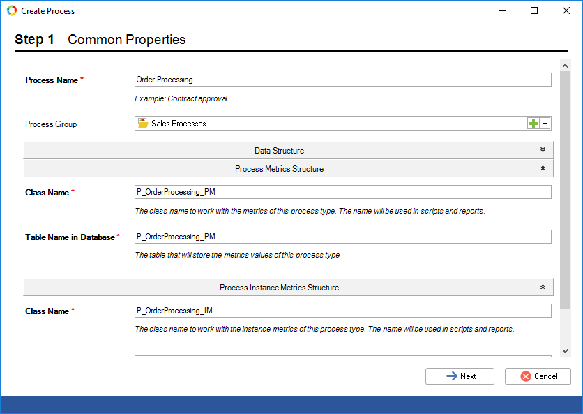
Fig. 5 ELMA Designer. Creating a process
Step 1. Common Properties:
- Process Name. The name is displayed in the process list in the Designer and the Web Application.
- Process Group. Use the drop-down list to select the process group or click the plus icon to create a new group. Select All Processes to save the process in the Process List.
Click Next to continue.
Step 2. Swimlanes
Select and add business process participants. Use the organizational structure created and published before. You can see the Organizational Structure in the left part of the dialog box.
The sample configuration contains an Organizational Structure.
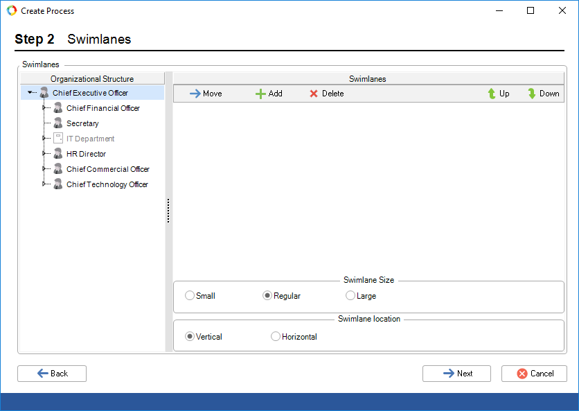
Fig. 6 ELMA Designer. Creating a process
To add a process participant, simply drag and drop the respective item of the organizational structure to the Swimlane area to the right. Alternatively, click the Add button and in the emerged window select a participant.
By using the Add button, you can select different swimlane types. For example, you can select a dynamic swimlane, which allows you to select a task executor in course of a process. If your process involves a lot of paperwork, you will need a business role swimlane that is used with document management activities. Learn more about swimlanes in ELMA Help.
Once you have selected the business process participants, click Next to finish the Process Creation Wizard.
ELMA Designer will create a new business process with the start event and the swimlanes defined at Step 2 of Process Creation Wizard.
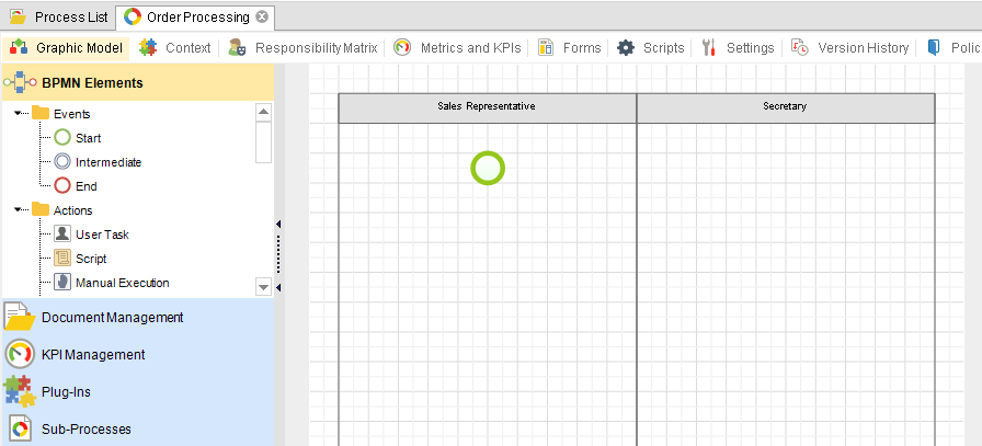
Fig. 7 ELMA Designer. Process Graphic Model
1.3 Describing workflow
The next step is to describe your workflow. A workflow can be represented as a chain of connected activities. To create an activity drag an appropriate element from the left Toolbar and to a swimlane.
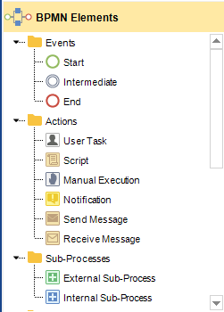
Fig. 8 ELMA Designer. Activities panel
The Toolbar contains the list of all available operations (activities, events, gateways, etc.). Operations are grouped by type.
You can find the detailed information about all the operations in ELMA Help.
We recommend that you start modeling with a User task. It’s the most simple and widely used task type. A User Task is work that must be done by a user. When users finish their work, they must enter certain information in a form and click one of the available buttons to continue.
Drag a User task activity from the Toolbar and to the Swimlane, which represents a user who has to perform the task. By default, ELMA generates the name of the User task (Task 1). You can change this name later.
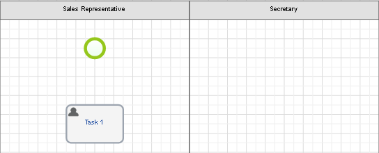
Fig. 9 ELMA Designer. Graphic Model
1.4 Configuring User Task
To configure a task, double-click on the task shape on the modeling sheet. The following settings window will open:
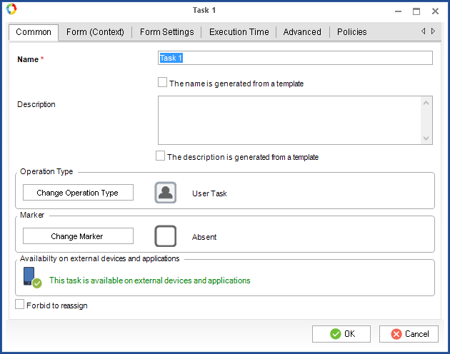
Fig. 10 User task settings. Common tab
The settings window has several tabs with different settings.
On the ‘Common’ tab, you can enter a task name and a task description. A user will be able to see this information when they are assigned a task.
On the ‘Form (Context)’ tab, you can specify what information is provided to a user and what information they will need to enter to the system once they complete the task.
Below is an example of a task context:
.png)
Fig. 11 User task settings. Form (context) tab
The left column contains a list of all the variables involved in the process, the right column shows all the variables used in the task.
You can mark each variable as Required or Read Only. If you check the ´Required´ box, a user will not be able to complete the task until they specify the value of this variable.
The ‘Read Only’ option forbids anyone from making any changes to the variable. The users receive task data for informational purposes only.
Initially, the list of variables is empty. To add a new variable, click Add at the top of the settings window. A dialog box opens:
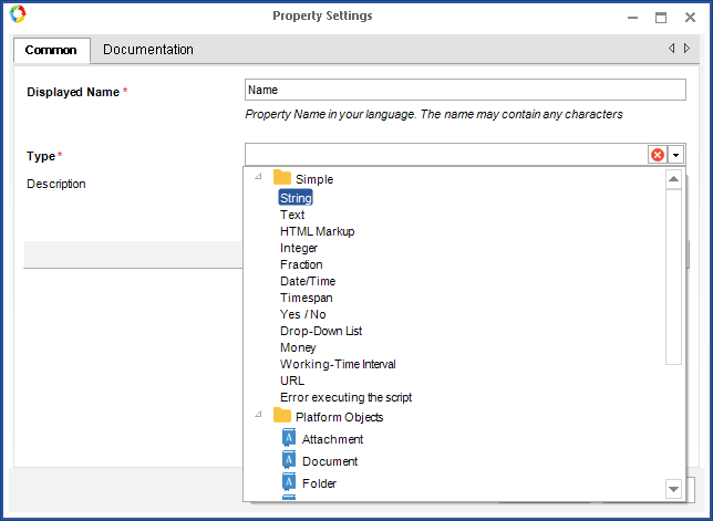
Fig. 12 Property Settings dialog box
In the Displayed Name field enter the name of the variable and select the variable type in the drop-down list. ELMA supports different variable types. To select a type, consider the information, which will be stored in the variable. For example, use ´String´ to store names, ´Integer´ to store numbers and ´Date/Time´ for dates.
Once you have chosen a variable type, you can specify additional properties. For instance, you can set the default value for the Integer or a date format for the Date/Time variable type. Create as many variables as you need. In the web portal, a user will see the following task form:
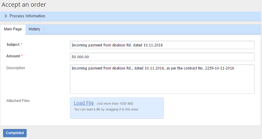
Fig. 13 Process task page
Two fields on the screenshot Name and Amount are required. The fields’ names appear in bold and have a red asterisk next to them. A user will not be able to complete a task until they fill in the details. The other tabs of the settings window allow you to set the task deadlines, configure the task form and much more. Learn more about task settings in ELMA Help.
Similarly, you can add other activities to the process model. If necessary, you can move the activities from place to place, using drag and drop.
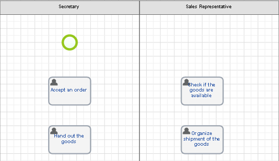
Fig. 14 ELMA Designer. Graphic model
1.5 Activity connectors
After you have arranged process activities in the graphical model, link them with Connectors. Connectors define the order of the flow objects. To link two flow objects, move the mouse pointer to the edge of the first flow object - a small red square will appear next to the mouse pointer; it is a connection point. Click and hold the left mouse button and draw the connection toward the second object. Another red square will appear on it. To connect two objects draw a line to that point. ELMA will create a connector when you release the mouse button. Each connector has an arrowhead, which shows the order of the flow elements. On the screenshot, you can see how connectors link the start event and the first task.
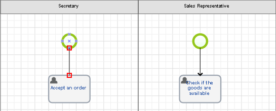
Fig. 15 ELMA Designer. Graphical Model
You have to connect all the activities on the process model. Some activities can have more than one incoming or outgoing connectors. For example, a User Task activity with various outgoing connectors implies that you must decide which path the process takes after this task is completed. The respective task form will have several buttons showing possible task outcomes. If you add other BPMN elements, you need to link them with connectors with as well. Once it’s done, add the end event to the model (an open red circle) and link it with a preceding task. The graphical model must not contain elements without respective connectors.
Below you can see an example of a complete process model:
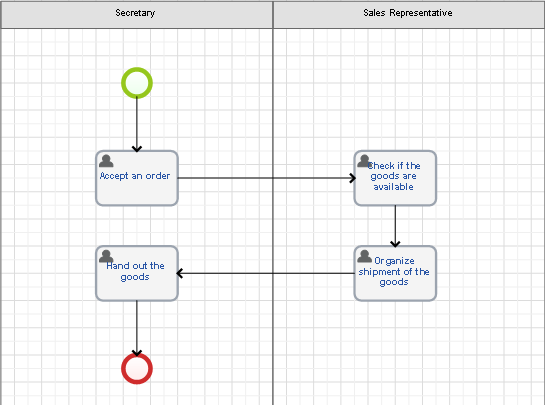
Fig. 16 ELMA Designer. Graphical Model
1.6 Configuring Connectors
Finally, specify the connectors’ names. Open the settings window by double-clicking the connector.
In the respective field specify the connector’s name and if necessary, leave a comment in the Description field. The information you type in this filed does not affect the process flow but serves as a reminder.
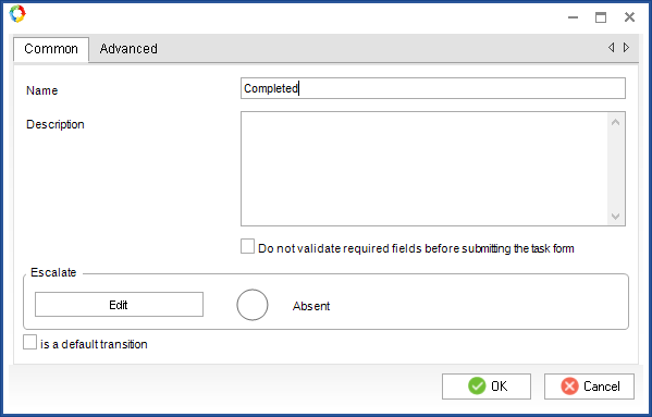
Fig. 17 ELMA Designer. Connector settings
We recommend that you always specify the names of the transitions because it increases the readability of the graphical model. The names of the connectors correspond to the names of the buttons on the task forms.
An example:
.png)
Fig. 18 ELMA Designer. Graphic model
1.7 Responsibility matrix
A responsibility matrix allows you to determine roles of the business process participants (task executors, supervisors, owners). To configure a responsibility matrix, go to the respective tab in ELMA Designer. Initially, a list of business process participants includes users represented by swimlanes.
There are four roles available:
- A participant is an executor of the tasks that make up the business process.
- An owner is a user fully responsible for the entire process. This means that the owner is responsible not only for the result (product) of the process but also for the process progress and the customer's satisfaction.
- An informed user does not perform any process activities but receives information about the process progress, status, significant changes, etc.
A supervisor is a user who has permissions to monitor the execution of the process. Usually, the supervisor is one of the company's executives.
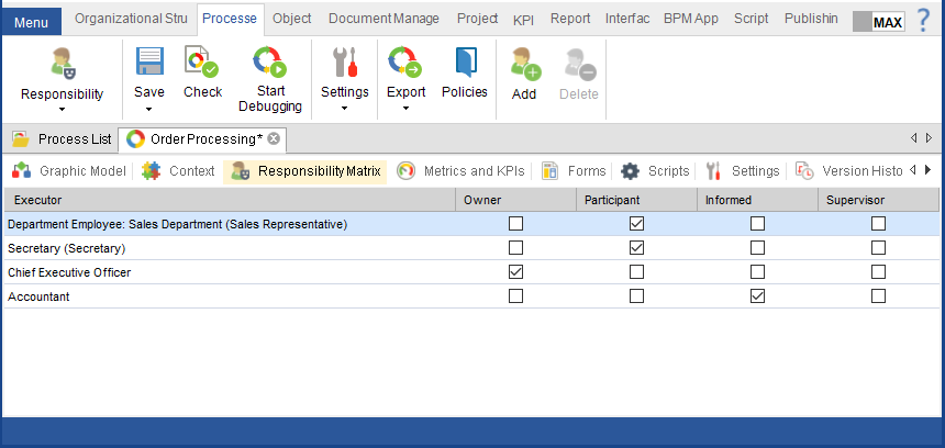
Fig. 19 ELMA Designer. Responsibility matrix tab
Use ‘Add’ or ‘Remove’ buttons to manage process participants and determine participant’s roles by checking the respective boxes.
2. Checking and Publishing Business Process
After you have designed the process model, you can check if it has logical errors, by clicking the Check button in the upper toolbar. If your process model is created correctly, you will see the respective system notification:
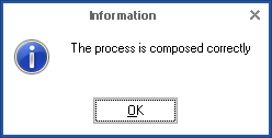
Fig. 20 Process check result
If the process model contains errors, ELMA will highlight the supposedly erroneous elements and provide a list of errors on the Errors and Warnings panel. If you click on the error in the list, you will see the respective element with red outlines. You will not be able to start the process until you correct all the errors.
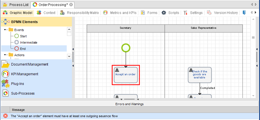
Fig. 21 ELMA Designer. Error when checking the process
Once the process is modeled and checked, you can publish it. You will not be able to run your process until it is published. To publish a process, click on the lower part of the Save button and in the context menu select Publish.
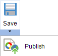
Fig. 22 ELMA Designer. The Publish Button
All the changes you have made will be applied once the process is published. Now you can run it in the ELMA web portal.
3. Starting Business Process
Business processes are executed in ELMA web portal. Only users with respective permissions can start processes. In the process model, these users are represented by a swimlane with the start event. Therefore, to be able to start a process, you need to log in to the system with the respective user account. There are several ways to start a process. The easiest way is to click the ‘Start Process’ button on the toolbar at the top of the main page.
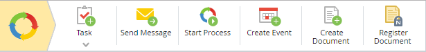
Fig. 23 ELMA web portal
A window opens showing all the processes you have permissions to start in a tree-like structure.
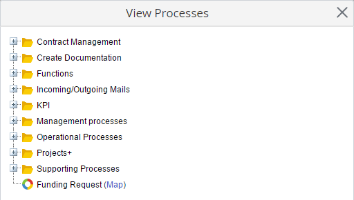
Fig. 24 ELMA web portal
To run a process, click on its name and confirm your decision, by selecting ´yes´ in the dialog box.
Before you start a process, you can check its map; it opens in a new browser tab. A process map looks like a process model, which you have created in ELMA Designer.
Once the process is started, you have to specify the name of the process instance. Since one business process can be run simultaneously by multiple users, each process instance must have its unique name to distinguish one instance from another. In order to avoid possible confusion, we recommend choosing simple and understandable names.