Organizational Structure Modeling
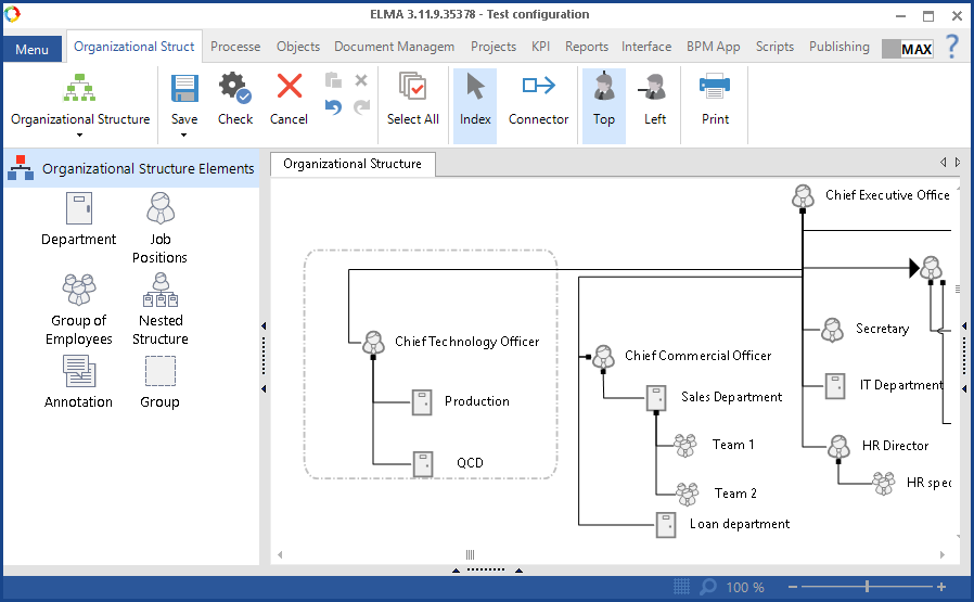
Modeling the organizational structure of a company is one of the first steps in implementing ELMA. It is done in ELMA Designer, on the Organizational Structure tab (Fig. 1).
Modeling the organizational structure means creating a graphic model of a company's management structure (Fig.1).
A graphic model is shows the hierarchy of departments, job positions, etc. of the company.
|
Attention!
Please note, that the organizational structure modeling sheet can contain only one model. A model can have only one head element!
|
|
|
|
Fig. 1. Model of the Organizational Structure .
|
Organizational Structure Elements
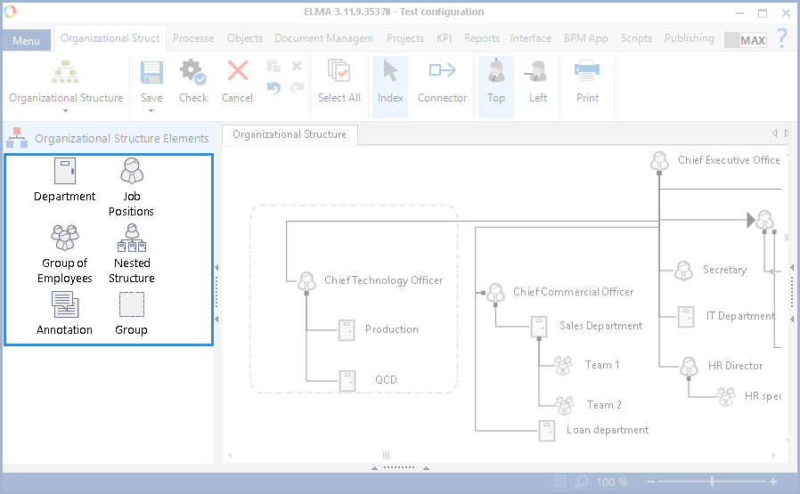
Organizational Structure Elements represent the structure of a company (departments, job positions, groups of employees), and increase the model's readability (nested structure, annotation, group) (Fig. 2).
|
|
|
Fig.2. Organizational Structure Elements panel.
|
The following elements are used to create an organizational structure model:
|
Graphic Element
|
Description
|
|
|
Department. The element settings must include only one Head and any number of employees. The number specified in the Number of Employees field has only the informative purpose.
|
|
|
Job Position. In the settings window of this element, you can assign a specific job position to this element. You can assign only one employee to one job position element.
|
|
|
A Group of Employees is a list of users with similar duties. Supervisors are not assigned to groups of employees.
|
|
|
A Nested Structure allows you to create nested organizational structures models. To do this, in the settings window click Go to the nested structure. It describes a part of the company's structure as an individual model. If the company has a complex multilevel organizational structure, the nested structure will make the model more readable. It is especially useful, if the company branches are located in different cities and you need to create a complex multilevel organizational structure.
|
|
|
Annotation allows you to add a comment to any element on the modeling sheet.
|
|
|
Group allows you to group certain elements in one box shape. It is useful if you want to group various departments by a certain attribute. For example, you can group the Financial and the Economics departments into one "finance group". This makes the model more readable.
|
|
|
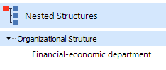
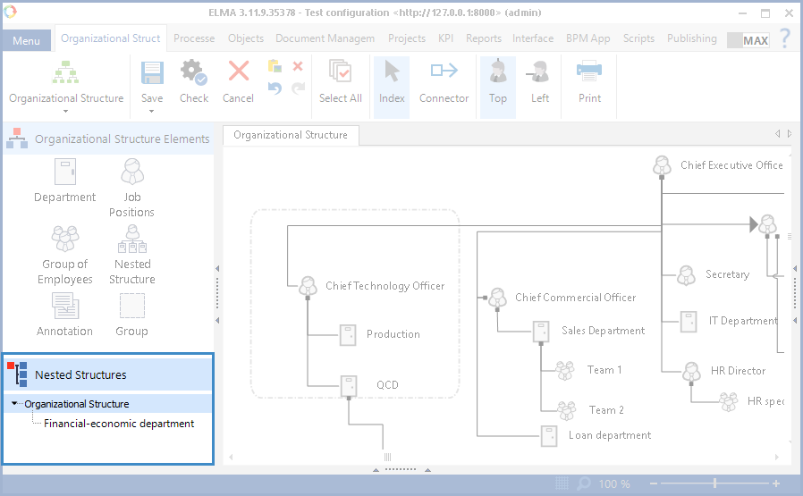
The Nested Structures tab contains a list of the model's nested structures. This tab appears in the Organizational Structure Elements panel once the Nested Structure element is added to the sheet (Fig.3.).
|
|
|
|
Fig.3. Nested Structures section in the Organizational Structure Elements panel.
|
To create a graphic model, drag and drop elements from the toolbar to the modeling sheet.
Adding organizational structure elements to the modeling sheet
Organizational structure elements are dragged to the modeling sheet from the Organizational Structure Elements panel.
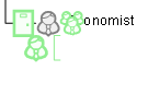
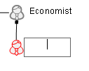
There is another way to add an element to the modeling sheet (Fig. 4). Click the Index button, then mouse over an element that is already on the modeling sheet. Green icons will appear around the element. Now drag one of them to the required place. A field for entering the element name will appear automatically, as well as a connector to this element (Fig. 5). The Top and Left buttons allow you to choose how the element is connected - from the top  of from the left
  .
.
|
|
|
Fig. 4. Adding an element of the organizational structure to the modeling sheet.
|
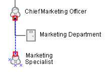
Selecting elements
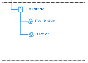
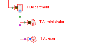
To select an element on the modeling sheet, mouse over it and press the left button on the mouse (Fig.6). To select several elements at once, press and hold Ctrl and left-click on each of the desired elements. If you hold the left mouse button and select a specific area of the modeling sheet, you will automatically select all the elements within that area. While you are selecting the elements, they are highlighted blue (Fig.7). The elements that are already selected are highlighted red (Fig.8). You can move or delete a group of selected elements.
|
|
|
Fig.6. Selected element of the organizational structure.
|
|
|
|
Fig.7. A group of elements within the selected area.
|
|
|
|
Fig.8. Selected group of elements.
|
Connecting elements
The relation between a superior and subordinate elements is shown with a connector in the graphic model. The superior element has a black dot in the beginning of the connector (Fig. 9).
|
|
|
Fig. 9. Connection of two elements. Supervisor element.
|
When you add a new element to an existing element, a connector is created automatically.
When you add a new element from the Organizational Elements side panel, you need to select the Connector tool in order to create a connector. Then mouse over the element, out of which the connector will go. Connection points will appear. When you mouse over such a point, it turns into a red square (Fig.10). To create a connector, press and hold the left mouse button and draw a line to a connection point of the element that you want to link.
|
|
|
Fig.10. Connecting two elements of the organizational structure.
|
Moving elements
To move an element, select it, press and hold the left mouse button and drag the element to the required area of the modeling sheet.
Changing names and descriptions of organizational structure elements
To open an element settings window, mouse over the element and right-click on it. Then select Settings in the context menu (Fig.11).
To change the element's name double-click on its name.
Deleting organizational structure elements
To delete an element from the modeling sheet, select it and press Delete. You can also delete the element from its context menu.
If the organizational structure model is published, the system will show a warning where you will have to confirm or cancel deleting (Fig.12).
|
|
|
Fig.12. Notification when deleting.
|
If you click Check Usage, the system checks if the element is currently being used by ELMA applications. After checking, the Configure an organizational structure element window opens. It has two tabs, by default the Usage tab opens. The usage check feature is described in the Search of organizational structure elements section.
When you click Delete, the element is deleted from the modeling sheet, and its usage is not checked:
-
If the deleted element used to represent a job position, the users who are assigned to this job position will be removed from it;
-
If the deleted element was used in business processes to specify an executor of a swimlane, the tasks of this executor in all the process instances will be reassigned to the user responsible for the process instance. In this case, ELMA will show a notification (Fig. 13):
|
|
|
Fig.13. Notification about the task being reassigned.
|
-
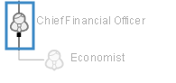
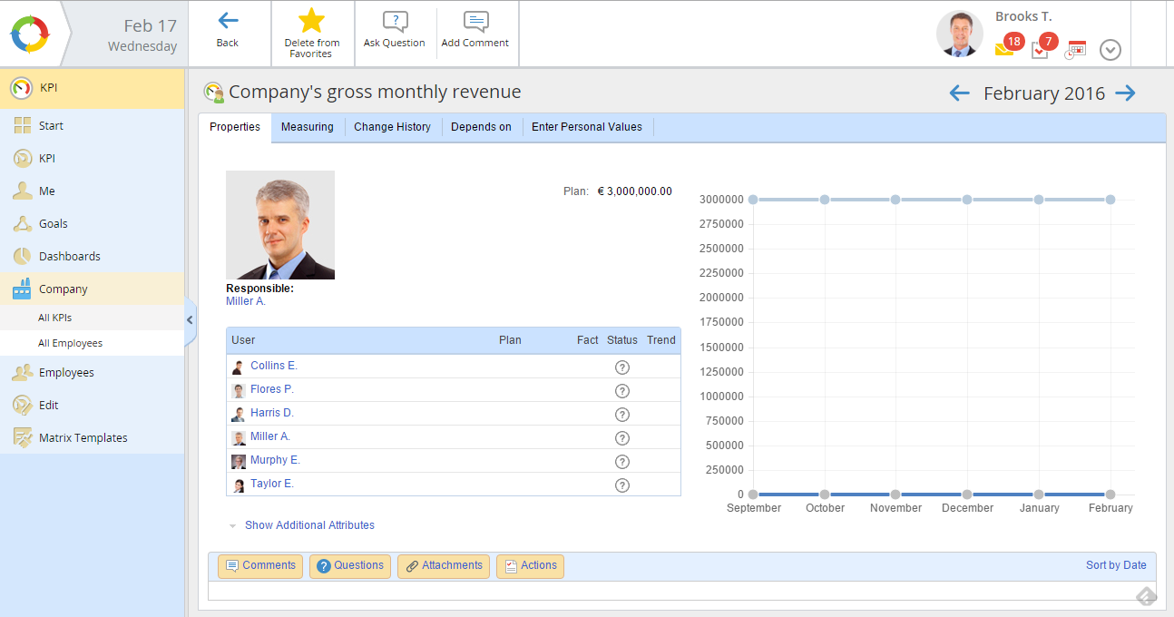
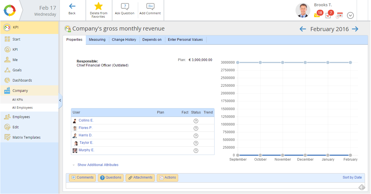
If the element was used by the ELMA KPI application, the latest KPI values for this job position will be saved (Fig. 14 and 15).
|
|
|
Fig. 14. KPI of a job position before it is deleted.
|
|
|
|
Fig. 15. KPI of a job position after it is deleted.
|
If you click Cancel the window for deleting the element will close, and the element will not be deleted.
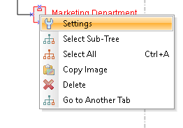
Element's context menu
The context menu contains a list of controls that allows you to manage the element.
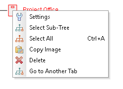
To open the context menu, right-click on an element (Fig. 16).
-
-
Select Sub-Tree – select the current element and all the elements below it in the structure's hierarchy. If there are no such elements, then only the current one will be selected.
-
Select All – select the whole organizational structure tree. You can also do it by pressing Ctrl + A.
-
Copy Image – the image of the element is copied to clipboard.
-
Delete – delete the element from the modeling sheet.
-
Go to Another Tab – this option opens the Selecting a nested organizational structure window (Fig.17).
|
|
|
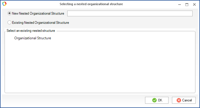
Fig.17. Selecting a nested organizational structure window.
|
In this window you can move the current element into any nested structure.
Select Existing Nested Organizational Structure and the desired structure in the Select an existing nested structure field. When you click OK the element is automatically moved to the modeling sheet of the nested structure.
If you want to add the element to a nested structure which is not yet described on the modeling sheet, select the New Nested Organizational Structure option and type in its name. When you click OK, the new nested structure will replace the element in the modeling sheet, and the element itself will be moved to the modeling sheet of this newly created structure.
Scale of the graphic model
There are two ways to zoom in/out the graphic model of the organizational structure.
1. Use the slider in the right corner of the status bar of ELMA Designer (Fig.18).
|
|
|
Fig.18. Slider for scaling.
|
2. Press and hold Ctrl and scroll the mouse wheel over the modeling sheet.
Changing the size of the modeling sheet
If the size of the modeling sheet isn't enough for the complete organizational structure tree, you can make it bigger. Place the mouse over the bottom or the right edge of the sheet: a blue indicator will appear. Click on it and drag it resize the sheet. This indicator only appears on the bottom (Fig.19) and the right (Fig.20) edges of the modeling sheet.
|
|
|
Fig.19. Bottom indicator.
|
|
|
|
Fig.20. Right-hand side indicator.
|
Using the grid mesh of the modeling sheet
To turn the grid mesh on or off, click on the mesh button ( ) in the status bar located in the right corner at the bottom of the page. You might want to turn the mesh off when exporting the model as an image.
See also:
Copyright © 2006–2019 ELMA